If you’ve played around with hobby electronics/robotics you’ve probably come across a servo motor, most commonly a rotational one. Unlike a standard DC motor these devices have built in control logic to reach a specific angle (Sparkfun, n.d.). A very relevant application is in the steering of a remote-controlled car where a wiper is used to alter the angle of the front wheels, kind of like the steering wheel in a real car.
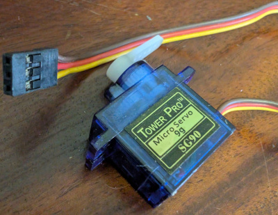
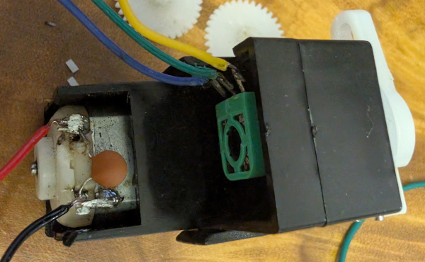
Most hobby servo motors (like the one in Figure 1) have 3 wires, two for power and another for control. In fact, these are so common that there is an Arduino library1 for this. But when I pulled apart my remote controlled car there were 5 wires (Figure 2), what’s that all about?
5 Wire Servos
Despite me referring to these as servo motors, they’re not really. They are very similar to a 3 wire hobby servo, but they lack the control logic for reaching a target angle. In the case of my RC car this would have been implemented on the original control board, so I’ll need to implement this control myself.
Initially, I didn’t know what all of these wires were for so I did some googling and came across a thread on the Arduino Forums2. The answer from johnwasser (2021) suggested that this was a DC motor with a feedback potentiometer. And looking closely at the original control board I was able to relate this to my rc car.
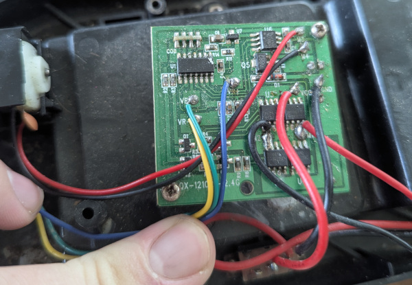
In Figure 3 the yellow, green, blue wires and the two thin red and black wires at the top attach to the steering servo. The labelling of the contacts on the PCB give it away, the red and black wires are connected to M3 and M4 where I’m guessing M is for Motor (the drive motor was on M1 & M2). The yellow and blue wires are on VR- and VR+, respectively. The green wire was attached to VR, and it seems like VR could mean Variable Resistor. Also telling was that in Figure 2 the yellow, green and blue wires were attached to a separate electrical device to the red and black wires which are definitely attached to a motor.
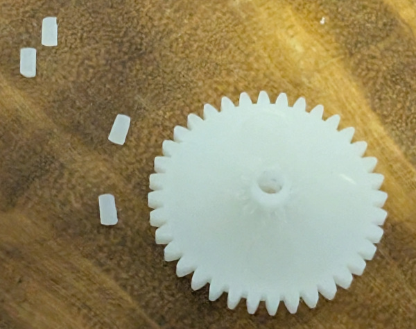
With the wiring worked out I desoldered the wires and stripped them back a little. I also spread a little lead-free solder on the ends to make it more breadboard friendly3. I actually started this over a month ago and wrote some very basic control logic for the spare Arduino Mega knockoff I had. I hooked it up to an L298N motor driver I had (would not recommend for new projects) and started playing around with working out what range of potentiometer values I would get. I then implemented a naive controller where I would turn the motor at a fixed pwm until I reached the desired potentiometer reading. This was pretty good, and I tried to refine it as much as I could and during that process I heard a crunch and the wiper stopped turning. Upon inspection I found that the gear was stripped (see Figure 4).
Replacing Gears
This was bound to happen in my experimentation. Since the servo has physical blocks to prevent it from turning too far, when I made an error in my logic and the motor would try to turn too far the internal gears would end up getting stripped. Like with the larger drive gear I decided to try and replace these with a 3d printed part which I quickly made in OpenSCAD thanks to the OpenSCAD Gear Generator library4.
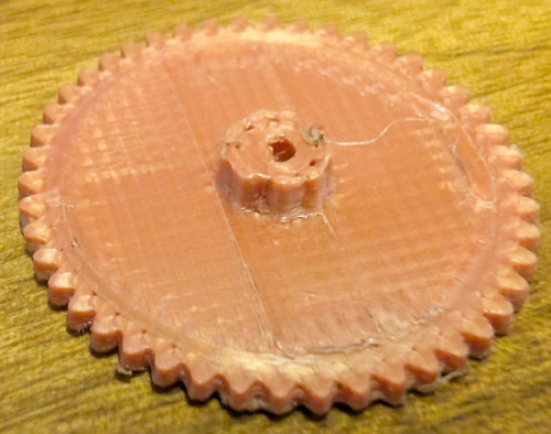
To my dismay, when printed in the Elegoo Silk Red Copper PLA filament the finer teeth turned out horribly (see Figure 5). It turned out more like a lumpy circle, I played around with some different settings but didn’t really get anywhere. So, I turned to AliExpress and got some really cheap that would suit my needs. I watched the shipping updates impatiently and waited and waited, until I got sick of waiting.
I’d recently bought some plain black Elegoo PLA which gave me much finer results for another project without needing to change any settings. I had another crack at printing the gear but it wasn’t quite there yet. I even asked an LLM for a bit of advice which suggested that there wasn’t enough cooling time between layers. To fix this I tried printing 4 at once. This did the trick! Funnily enough by the time I’d gotten that sorted the ones from AliExpress arrived anyway.
In this time I’d gotten a Raspberry Pi Pico 2 for some experimentation and thought that this could be a good project for it.
PID Control
In the time I spent waiting on replacement gears I researched better ways to control the servo. A common method of control is proportional integral derivative (PID) which uses three gain constants for minimising error over time (Hong 2023). It sounds fancy and complicated but it’s actually pretty straightforward to implement. In order to minimise \(e(t)\), we take a step \(u(t)\) as shown in Equation 1, sourced from Hong (2023) which I would recommend checking out. \[ u(t) = K_pe(t) + K_i\int_0^te(\tau)d\tau+K_d\frac{de(t)}{dt} \tag{1}\] There’s lots of fancy symbols in here that you might leave you wondering how to implement this in code.
Let’s start with working out the error, \(e(t)\). In our case we’re trying to control a servo and we know where it is based on a reading from the potentiometer. We’ll define \(\theta\) as the target potentiometer reading, and \(p(t)\) as the potentiometer reading at time \(t\). This gives the following equation for error: \[ e(t) = \theta - p(t) \tag{2}\] In the C code on a Raspberry Pi Pico 2 I would read \(p(t)\) from the ADC (analogue to digital converter):
const uint16_t pos = adc_read();
const float error = target - pos;
Why did I use a float for error? Because I’ll be using floats later on so this will keep the types consistent. Note that you cannot make error a uint16_t as it needs to be signed to determine the direction to turn the motor.
The constants \(K_p\), \(K_i\) and \(K_d\) are gains that we get to choose by tuning and we’ll get into that a bit later. So now we have everything we need to calculate the first term of Equation 1:
#define KP ...
float u = KP * err + ...;
The second and third terms are known as the integral and derivative terms, looking closely at the integral term we see this integral: \[ \int_0^t e(\tau)d\tau \tag{3}\] Integrals are just a fancy term for a big sum over a continuous variable, in this case time. We can view this term as the total error accumulated since the target was set up until this point. Now, you’ll probably notice a problem here: we can’t measure the error continuously, it’s impossible. Thus, we measure at discrete time intervals, for consistency we should make this interval constant. Let’s call this time between readings \(\Delta t\), I used \(\Delta t = 0.001\) seconds but we can probably get away with a bigger interval Thus, we have replaced \(dt\) with \(\Delta t\). In code it would probably look a bit like this:
#define KI ...
#define DELTA_T 0.001f
// Somewhere global
float total_error = 0;
// ...
// In when we update the servo every Delta t seconds
total_error += error;
float u = KP * error + KI * total_error * DELTA_T + ...
But how do we actually get this to run every \(\Delta t\) seconds? Through timers, specifically the repeating timer functionality provided by pico/time.h. Through this functionality we can have a function called at a fixed interval. For example:
#include <pico/stdlib.h>

#define SERVO_PERIOD 1000 // 0.001s

typedef struct servo
{
    uint16_t target;
    float total_error;
} servo_t;

bool update_servo(repeating_timer_t *rt);

int main()
{
    // Initialise the servo
    servo_t servo;
    servo.target = 2048;
    servo.total_error = 0;

    repeating_timer_t timer;
    if (!add_repeating_timer_us(-SERVO_PERIOD, update_servo, &servo, &timer))
    {
        printf("Failed to initialise timer\n");
        return 1;
    }

    while (1) {}
    return 0;
}

bool update_servo(repeating_timer_t *rt)
{
    // Use seconds for time
    static const float dt = (float)SERVO_PERIOD / 1e6f;

    servo_t *s = (servo_t *)rt->user_data;
    // Calculate error, u(t), etc.

    return true; // keep the timer going
}
This is all pretty much ripped from the official examples, though you may be wondering why I call add_repeating_timer_us with -SERVO_PERIOD instead of SERVO_PERIOD. The sign of the time changes how it is counted: positive values will cause the timer to restart after the callback has completed, while negative values will cause the timer to restart once finished (Sanderson 2020).
Finally, we have the derivative term. Since we are using discrete time intervals we make the following approximation: \[ \frac{de(t)}{dt}\approx\frac{e(t) - e(t - \Delta t)}{\Delta t} \tag{4}\] This is the backward finite difference, and to implement this in code we’ll need to keep track of the error from the previous step:
typedef struct servo
{
    uint16_t target;
    float total_error;
    float previous_error;
} servo_t;

// ...

bool update_servo(repeating_timer_t *rt)
{
    // ...
    const float derr = error - s->previous_error;
    float u = KP * error + KI * s->total_error * dt + KD * derr / dt;
    s->previous_error = error;

    // update motor, etc.

    return true;
}
And that’s pretty much it for the PID code, now let’s take a look at the hardware.
Hardware
I ditched the Mega and L298N for the Raspberry Pi Pico 2 and the TB6612FNG motor driver. The choice of motor driver isn’t too big of a deal, any H-bridge should work providing it supports 3.3V logic. I chose the TB6612FNG because of all of the drivers I have it is the most modern and efficient, though I acknowledge that there are even better motor drivers and will probably upgrade sometime down the track. I set this up on a breadboard while I test but I’ll probably move to a custom PCB at some point, Figure 6 shows how I had everything set up.
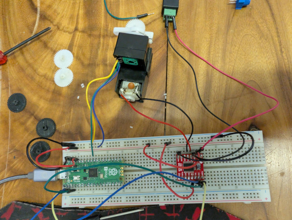
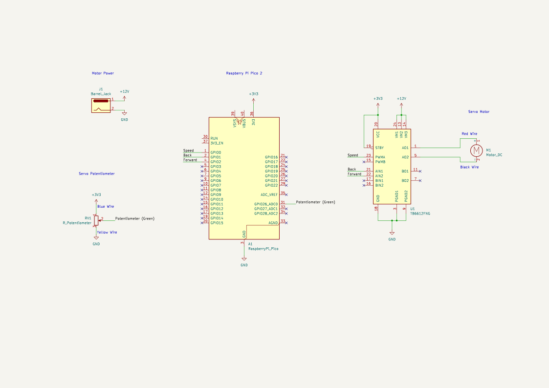
I used GPIO pin 26 on the Pico 2 for the potentiometer input as it is connected to channel 0 of the Analog to Digital Converter (ADC). I used GPIO 0, which is in PWM slice 0, channel A for the speed control. I used GPIO 1 & 2 for the direction controls, but these pins don’t need any special features. I powered the DC motor from an external 12V 5A DC power supply, while the Pico was powered over USB. To create a common ground I connected the grounds of both power supplies. Figure 7 shows a schematic of my setup.
Controlling the Motor
Calculating \(u(t)\) is all well and good, but how do we translate that into actual movement? My solution was to use the magnitude of \(u(t)\) to determine the speed and the sign to control the direction. We can write that in code like this:
// In update_servo
// ...
float u = ...;

if (u < 0)
{
    gpio_put(2, false);
    gpio_put(1, true);
    u = -u;
}
else if (u < 0)
{
    gpio_put(1, false);
    gpio_put(2, true);
}
else
{
    gpio_put(1, false);
    gpio_put(2, false);
}

pwm_set_chan_level(0, PWM_CHAN_A, (uint16_t)u);
If you used this code with the default PWM configuration from pwm_get_default_config() you would, like me find that the motor would make a lot of noise. That’s because the frequency lands right in the audible range for humans. With no clock prescaling we can reduce the PWM frequency by reducing the wrap value, this does come at the cost of some resolution. With the settings I used I went from 16-bit to 12-bit resolution (which is still better than the 8-bit resolution on AVRs) and was good enough for my use case:
// In main
// ...
gpio_set_function(0, GPIO_FUNC_PWM);
pwm_config conf = pwm_get_default_config();
pwm_config_set_wrap(&conf, 4095);
pwm_init(0, &conf, true);
With the reduced 12-bit resolution we need to adjust the code in update_servo:
// ...
pwm_set_chan_level(0, PWM_CHAN_A, (uint16_t)(u > 4095 ? 4095 : u));
Now that I could control the motor it was time to tune the PID controller.
PID Tuning
There are three constants that we can tune to optimise the PID controller: proportional gain (\(K_p\)), integral gain (\(K_i\)) and derivative gain (\(K_d\)). To find these we need a way to command the servo and analyse error. Luckily this is fairly easy on the Pico, by using the USB serial port we can write out the error values and monitor them over time. I just hardcoded a target (which I had to change every time) and printed error to the console. However tempting it may be don’t call printf in the repeating timer callback! Why? Remember how we configured the timer callback to be called no matter whether the previous callback had finished or not? We can easily lock up the CPU if the callback takes too long. I ended up just doing this in the main loop:
/// ...
int main()
{
    // ...
    while (1)
    {
        printf("Error = %f\n", servo.previous_error);
        sleep_ms(100);
    }
}
Following Hong (2023), I first tuned the proportional gain, by setting \(K_p=1\), \(K_i=0\) and \(K_d=0\). \(K_p=1\) resulted in a very small \(u(t)\) which wasn’t enough to move the motor so I threw \(K_p=10\) at it which gave really snappy movement. This did result in a bit of overshoot and I found \(K_p=5\) to be the smallest value I could use where the motor would still move. Watching the error for a while, I observed that the error didn’t quite settle at zero, it would be consistently off by a certain amount. This is called steady-state error and will be eliminated by the integral term (Hong 2023).
With \(K_p=5\), I moved on to tuning \(K_i\). I naively started with \(K_i=1\), which immediately resulted in another gear being stripped. I then tried very small values of \(K_i\) before settling on \(K_i=0.15\) which seemed to reduce the steady-state error by a bit without threatening to destroy another gear. Finally, I tuned the derivative gain (\(K_d\)) which accounts for future error (Hong 2023). Having learned my lesson with \(K_i\), I started small with \(K_d=0.01\) since large values can result in oscillations (Hong 2023). This gave me much better error but it was oscillating a bit, so I tried \(K_d=0.005\) which gave \(|e(t)|\leq 20\). Though this wasn’t as good as \(K_d=0.01\), so I played around with some values in between before landing on \(K_d=0.006\).
Code Refactor and Improvements
Now that I had a working setup I decided to clean up the code a bit, by splitting all of the steering stuff into it’s own module. I won’t paste all of the code here but it is available in my Codeberg Repo for the project. The main thing I did was create a struct which contained all of the necessary configuration data and a builder API to handle proper configuration. In the end I had a clean main.c which could set the servo position based on serial input:
#include <stdio.h>
#include <stdlib.h>
#include "hardware/adc.h"

#include "steering.h"

#define KP 5
#define KI 0.15
#define KD 0.006

int read_int(uint digits);

int main()
{
    stdio_init_all();

    // Initialise ADC
    adc_init();

    // Initialise Steering
    steering_motor_t steering = steering_init();
    steering_set_pin_pot(&steering, 26);
    steering_set_pin_speed(&steering, 0);
    steering_set_pins_dir(&steering, 2, 1);
    steering_set_gains(&steering, KP, KI, KD);
    steering_set_limits(&steering, 2048, 512);
    steering_set_deadband(&steering, 20);
    steering_set_target(&steering, 2048);
    if (!steering_begin(&steering))
    {
        printf("Failed to initialise steering!\n");
        return 1;
    }

    while (true)
    {
        int target = read_int(4);
        if (target > 4095) target = 4095;
        steering_set_target(&steering, (uint16_t)target);
        printf("\nTarget: %u\n", steering.pot_target);
    }
}

int read_int(uint digits)
{
    char buffer[digits + 1];
    uint i = 0;
    while (true)
    {
        int c = stdio_getchar_timeout_us(0);
        if (c == PICO_ERROR_TIMEOUT) continue;

        if (c == '\r' || c == '\n') break;
        if (i < digits && c >= '0' && c<= '9')
        {
            putchar(c); // echo back to serial
            buffer[i++] = (char)c;
        }
    }
    buffer[i] = '\0';
    return atoi(buffer);
}
I also added a configurable deadband to prevent the controller from trying to make impossibly small changes due to inconsistent error which was caused by inconsistent ADC readings.
Conclusion
In the end, I’m pretty happy with how this turned out. Yes, I could have just replaced it with a 3-wire hobby servo but it wouldn’t have been as much fun. I hope that this article is helpful for anyone else that wants to undertake this, I entered this with very little knowledge and am quite satisfied with my learning.
Next, I’ll need to work out a means to remotely control the car and a power source (probably 3x18650 cells). I’ll continue to post updates on my site on the project page.