After creating an IR barrier for detecting trains on my model railway I experimented with using this to control a train. For my most basic control I wanted the train to gradually slow down after passing through the barrier, stop for an amount of time and then gradually accelerate to top speed. This basically simulates a train stopping at a station, collecting passengers and leaving. I purchased a 12V 5A DC power supply to run the train (5A so I could expand to run a few in the future). I hooked this up to my TB6612FNG and because I needed some more pins I swapped out the ATtiny85 for an ATmega328P I recently found amongst my electronics stuff. Initially, I powered the atmega separately via usb, but that wasn’t good enough for me. I wanted to power the whole thing off one plug so I added an OKI-78SR-5/1.5-W36-C DC-DC buck converter to drop the 12V power supply down to a comfortable 5V for the atmega and the logic power for the TB6612FNG. Due to some concerns I had about how much power I was putting through the breadboard (maybe unfounded) I moved to a horrible cheap perfboard I had spare (Figure 1).
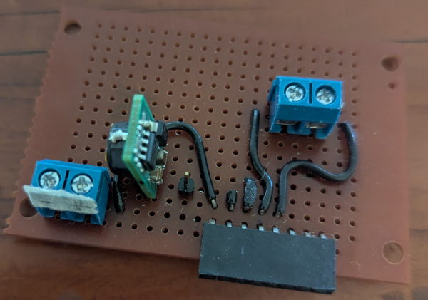
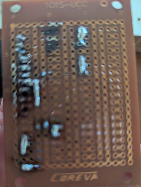
If you look at Figure 1 (b) you’ll see what I mean about how bad this board went - and it’s not entirely the board’s fault. I was using a cheap 30W soldering iron and no flux (apart from that in my solder) which meant that pads would lift before the solder had actually made a good joint. This caused me to move a lot of components around because of all of the damaged pads and traces. On top of that I needed to have a horrible mess of wires to hook up to the tracks, ATmega328P and the IR barrier (Figure 2).
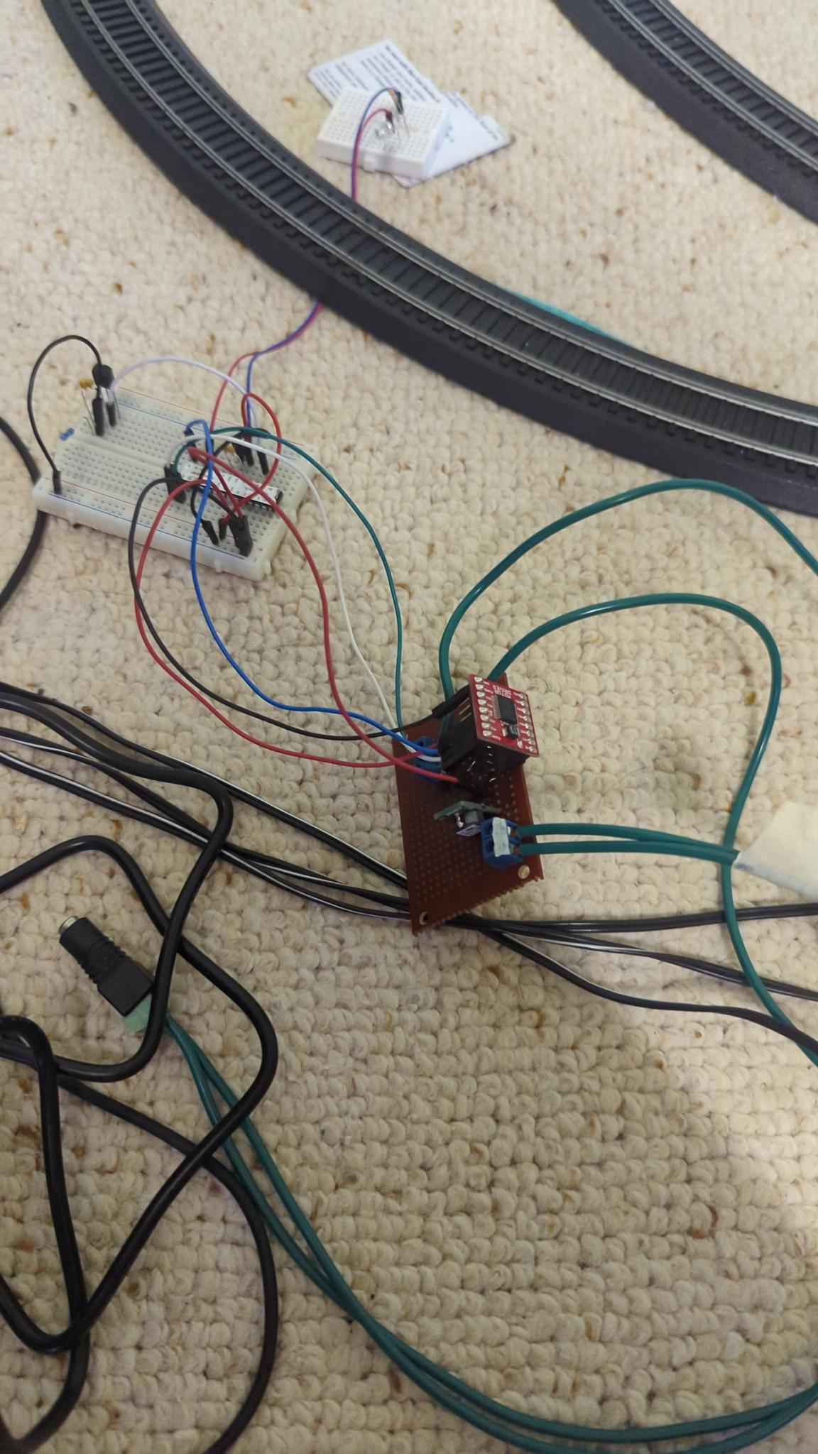
It does work though, and I guess that’s the point. I wrote up a program to handle my simple station simulation loop, which worked quite well and the train even stopped in the same spot consistently. The code isn’t terribly remarkable so I won’t post it in full but I used the INT0 interrupt to detect a break in the IR barrier:
ISR(INT0_vect)
{
    // When the train passes the sensor, tell it to stop
    if (state == TRAIN_FULLSTEAM && (PIND & (1 << PD2)))
        state = TRAIN_STOP;
}
And an enumeration to keep track of the train’s state:
enum train_state
{
    TRAIN_WAIT, // Wait for 5 seconds
    TRAIN_FULLSTEAM, // Accelerate up to full speed
    TRAIN_STOP // Slow down to a stop
};
In the main loop I would gradually apply constant accelerations depending on the target state:
while (1)
{
    switch (state)
    {
    case TRAIN_WAIT:
        _delay_ms(5000);
        state = TRAIN_FULLSTEAM;
        break;
    case TRAIN_FULLSTEAM:
        while (OCR1B < 255)
        {
            if (255 - OCR1B < TRAIN_ACCEL)
                OCR1B = 255;
            else
                OCR1B += TRAIN_ACCEL;
            _delay_ms(200);
        }
        break;
    case TRAIN_STOP:
        while (OCR1B > 0)
        {
            if (OCR1B < TRAIN_DECEL)
                OCR1B = 0;
            else
                OCR1B -= TRAIN_DECEL;
            _delay_ms(200);
        }
        state = TRAIN_WAIT;
        break;
    }
}
This was great, but I want to control 3 tracks so an upgrade was needed, sticking with my ATMega328P and TB6612FNG I set about designing a custom PCB.
The Custom PCB
I’d already been using KiCAD as practice for creating schematics for my projects so I could pull things apart and put them back together again later if needed. I started by watching this video from Core Electronics, which while being quite fast-paced it certainly gave me inspiration and showed me what was possible. The most important step of course was to give it a name, I named it after “The Fat Controller” from one of my favourite kids’ shows: Thomas & Friends, which I figured was relevant since this board would be large, had a microcontroller and would be running a railway.
With the name out of the way, the first step was to draw up a schematic in KiCAD. I naively chose pins on the ATMega328P for the different functions and made heavy use of net labels to keep it looking clean. My final schematic is in Figure 3.
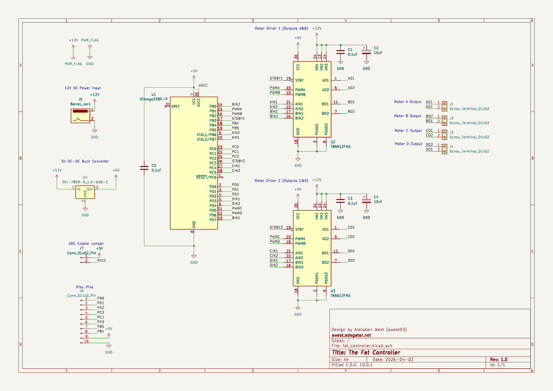
I chose to add a second TB6612FNG to the board so I could drive all three of my loops (and a fourth if I add one). I also exposed any pins I wasn’t using so I could expand in the future, taking special care to ensure that the USART pins would be accessible. I also added a jumper so that the ADC could be powered if needed in the future.
The next step was to check that my schematic passed the Electrical Rules Checker (ERC), which it initially didn’t as I hadn’t marked some pins as not connected and was missing the global power flags (top left of Figure 3). With the checks passed it was time to import the footprints into the PCB editor.
With the footprints copied over this is where the fun starts. I had to position every component manually and try to optimise the layout to make the routing easier. I this process I discovered that I had made some poor choices of pin allocations, so went back to the ATmega328P datasheet to see what pins I could change. I also had to ensure that the traces for the motor power were thick enough, which was easy enough to work out thanks to the Calculator Tools included with KiCAD. I even added the logo from the DHMO parody site adegator.net for bit of fun. The final PCB layout is shown in Figure 4.
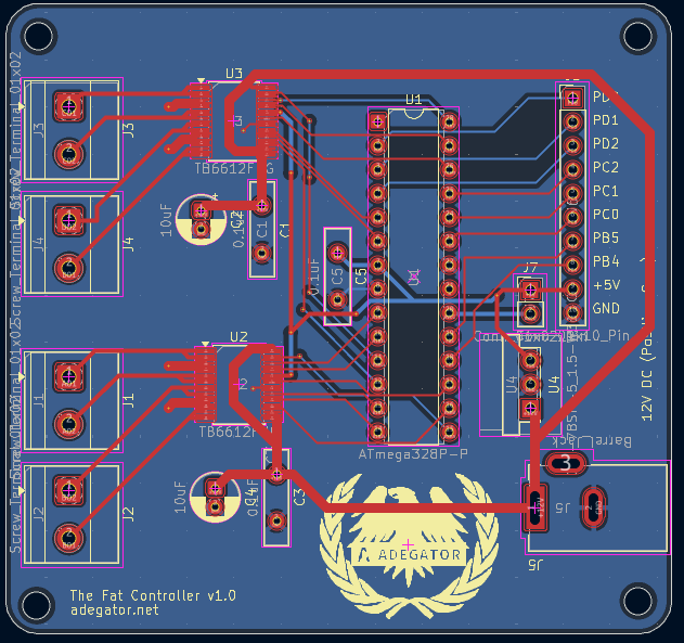
To reduce complexity and to aid in heat dissipation I made almost the entire second layer a ground plane. I also used through-hole capacitors so I could solder them easily and I had some on hand anyway. I submitted my design to JLCPCB to get it manufactured. I decided to wait until the boards arrived before ordering the TB6612FNG motor drivers, and I also ordered a new soldering station: The Geeboon TC22 off AliExpress which is rated for 220W and uses active tips so the temperature recovery times would be superior to my old cheap irons.
PCB Arrival
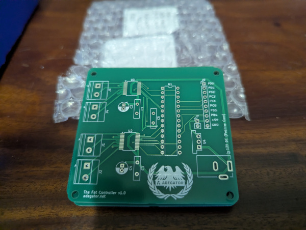
The PCBs turned up pretty quickly from China (I paid for the most expensive DHL shipping option, but I have no regrets). I did some continuity tests on the pcb with my multimeter to check that every connection worked as expected. And luckily it worked out! The freshly unboxed PCBs are shown in Figure 5.
I then ordered 4 TB6612FNG chips (some spares just in case) so I could complete the assembly. I got a bit bored waiting so I soldered on all of the through-hole components I already had (Figure 6). I got the screw terminals from some L298N modules I had ordered from Amazon on outdated advice, I also got most of the header pins from there too, as well as some others I had lying around. I got the barrel jack from an old Telstra T-Box streaming device I had kept for some reason, but this is when I discovered my first problem…
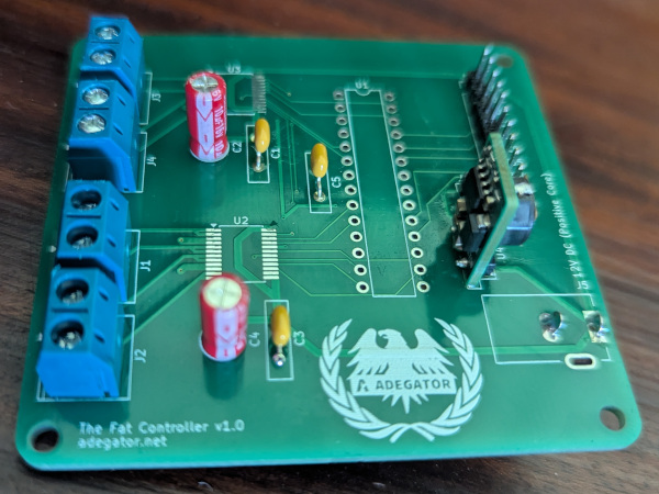
I had positioned the barrel jack footprint the wrong way around! I corrected this in Figure 4, but to deal with the problem I removed the side pin from the barrel jack as I wasn’t using it. I then soldered it onto the bottom of the PCB to get around the problem.
TB6612FNG Arrival
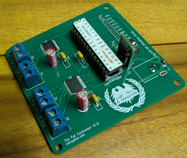
The TB6612FNG order finally arrived so I was eager to get those soldered on, but I was a bit naive as to how difficult that would be. I put a tonne of rosin flux (which on reflection I think went bad) on the pads and the chip and tried to tack the corners down. Once I had the corners down I tried to drag solder for the first time with a big knife tip. That went predictably bad so I tried using the conical tip to do pins individually and this made an even bigger mess. I then had to abandon that board and tried on another one. This time I tried to pre-tin all of the pads and then use the knife tip to heat one side at a time I positioned the chip. It looked like this was a success so I did it again for the second chip and transferred over all of the through-hole components. Figure 7 shows the final assembled version with the ATmega328P installed.
Testing
With everything fully assembled I popped out the ATmega328P and loaded a simple program to run all of the motors at max speed:
#include <avr/io.h>

int main(void)
{
    DDRB |= (1 << PB0) | (1 << PB1) | (1 << PB2) | (1 << PB3) | (1 << PB6) | (1 << PB7);
    DDRC |= (1 << PC3) | (1 << PC4) | (1 << PC5);
    DDRD |= (1 << PD3) | (1 << PD4) | (1 << PD5) | (1 << PD6) | (1 << PD7);

    // Pull Standby high
    PORTB |= (1 << PB3);
    PORTC |= (1 << PC3);

    PORTB |= (1 << PB7); // Send A forwards
    PORTD |= (1 << PD7); // Send B forwards
    PORTC |= (1 << PC4); // Send C forwards
    PORTD |= (1 << PD3); // Send D forwards

    PORTB |= (1 << PB1) | (1 << PB2);
    PORTD |= (1 << PD5) | (1 << PD6);

    while (1) {}
    return 0;
}
I then measured the voltage across each motor output. Outputs B, C, & D were working but A wasn’t. Testing with the multimeter revealed that some of the pins weren’t making contact with the pads, so weren’t soldered properly, even if invisible to the naked eye. I decided to get another bit of equipment: a hot air station. In particular the well-reviewed ATTEN ST862D which also happened to be on sale.
Once the hot air station arrived I tried reheating each chip and pushing it down a bit. I was able to straighten the second driver (outputs C & D) which was working anyway, but couldn’t get anywhere with the first driver. I ended up really messing it up even more with the soldering iron and breaking one of the leads before giving up. Something about having the right tools for the job anyway… I’ve bought some solder paste which might help me but these skills of course require constant learning and I’m definitely a beginner. Despite these challenges I’m still keen to keep going.
Smooth Motion Control
I decided to start making the program for the Fat Controller, or at least the motion control part of it. I could probably write a whole other post on this (and probably will), but I wanted to make the movement seem as smooth and realistic as possible. Thus I investigated constant jerk-based control. What is jerk? Jerk is the derivative of acceleration, or the rate of change of acceleration. This is analogous to how acceleration is the rate of change of velocity and velocity is the rate of change of position. You’ve probably experienced jerk before, a pretty common experience si how quickly you move the accelerator in a car. Tractors and lawn mowers can also be extremely jerky. My plan was to gradually increase acceleration at a constant rate (jerk) before reaching some maximum based on the train.
To handle these constant-time updates I used a timer interrupt on Timer 2 (since I was using Timers 0 & 1 for PWM). Every time that fires the acceleration is increased by a certain amount and the velocity is increased by acceleration, the PWM output is then calculated from the velocity. Unable to test this on real hardware I made a simulator in C to plot the PWM value over time in gnuplot.
Since the AVR has no floating-point hardware implementing this needed a bit of creativity. I used a 16 bit signed integer for velocity, but I only extracted bits 11-3 for the PWM value. Acceleration was an 8 bit signed integer and was added normally to the velocity. This is basically fixed point arithmetic, where the decimal point is in a different position for velocity and acceleration as shown in Figure 8.

Here’s an example of how I went about doing this in code:
int16_t velocity;
int8_t acceleration;
// ...
velocity += acceleration;
// Clamp velocity so the PWM bits don't exceed 255
// 2047 = (255 << 3) | (2^3 - 1)
if (velocity > 2047) velocity = 2047;
else if (velocity < -2047) velocity = -2047;
acceleration += 2;

// Apply PWM frequency
uint8_t pwm = velocity >> 3;
Reflections
I’ve had quite a bit of time to think about this project and what I’ll do differently in the future as I’ll probably end up making a V2. Here’s some of the things I’d like to change:
- Replace the ATMega328P with an RP2350: This is a pretty big change but would let me use floating point to handle smooth movement, especially with high resolution PWM.
- Use USB-C PD for track power instead of a barrel jack: This would allow me to use a greater variety of power supplies, it would also allow 15V which seems to be closer to what my Bachmann controllers put out. There are a few dedicated chips out there that can handle the PD negotiation logic so I will be looking into those.
- Look into modern MOSFET based motor drivers: Not entirely necessary but I only used the TB6612FNG because I already had one on a breakout to test with, but it seems that there are much more recent ones available which should give some efficiency gains.
I’ve also been reflecting on the ATtiny85 IR barrier and what I will do for train detection. I’ve done some experimenting with reflective sensors and I’ve come to the conclusion that if I can mount those on gantries above the tracks it will look more subtle. I’m also going to get some modern AVRs for this job since I’ll need a few of these and I’ve got my eye on the AVR16DD14. An RP2350 would obviously be overkill for this. I’ve also been looking into communication protocols between the sensors and the Fat Controller and I2C or similar could be a good option to reduce the number of wires needed.
This leads to another shortcoming of the Fat Controller: the SPI and I2C pins are being used for driving motors!
Anyway, I’ve learned quite a lot in this process and am looking forward to learning even more. This is a part of my ongoing model railway automation project where I’ll post more updates, I’m also working on a toy remote-controlled car at the same time.