Remote-controlled cars are fun, and the faster the better. We’ve been holding onto this 12V car for probably a decade now since we broke it. Over the years we’ve pulled it apart and had a poke around to see what was wrong. The control board was probably fried when it went through some water, but another issue was that one of the gears in the driving gearbox was stripped.
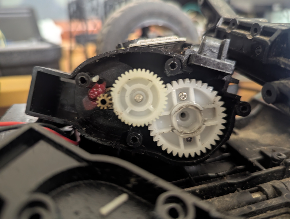
If you look closely at Figure 1 you’ll notice that the middle plastic gear is stripped near the small metal gear on the motor. Perhaps the wheels got jammed with the motor still spinning. Luckily it is fairly easy to model a new gear using OpenSCAD1 and the OpenSCAD Gear Generator library2. But how do we know what parameters to use?
The first parameter is the tooth count, I found that the best way to count the teeth was to take a photo of the gear and then open it in GIMP, Paint or similar and mark each tooth as you count it. The part I was replacing had a two gears on it, the larger one visible in Figure 1 and a smaller one on the other side. The larger gear had 40 teeth and the smaller one had 12 teeth, where the teeth were stripped I made an educated guess based on the assumption that the teeth were evenly spaced.
Next I took some measurements of the gears. The diameter of the hole was 4mm, this corresponds to the ‘bore’ of the gears. The large gear was 6mm high and the smaller one was 8mm high.
Finally, we need to know the gear ‘module’ which is the ratio of the gear diameter and the number of teeth (Worth 2024). This can be found through Equation 1: \[ \text{Module [mm]} = \frac{\text{Diameter [mm]}}{\text{Number of Teeth}} \tag{1}\] The outer diameters (including teeth) for the large and small gears were 21mm and 11mm, respectively. Rounded to one decimal place I found that larger gear had a module of 0.5mm and the smaller gear 0.8mm.
In my original design I neglected to include a large cavity on the underside of the gear to allow for the RC car’s housing. Since this would need to be on the underside while 3D printing I cut a conical shape from the bottom. This created a gradual reduction which resulted in a reasonably clean print.
include <gears.scad>

bore = 4;
big_modul = 0.5;
big_teeth = 40;
big_height = 6;
small_modul = 0.8;
small_teeth = 12;
small_height = 8;

difference() {
    union() {
    spur_gear(modul=big_modul, tooth_number=big_teeth, width=big_height, bore=bore, pressure_angle=20, helix_angle=0, optimized=false);

    translate([0, 0, big_height])
    spur_gear(modul=small_modul, tooth_number=small_teeth, width=small_height, bore=bore, pressure_angle=20, helix_angle=0, optimized=false);
    }
    translate([0, 0, -0.1])
    cylinder(5.1, 6, 4.5, $fn=50);
}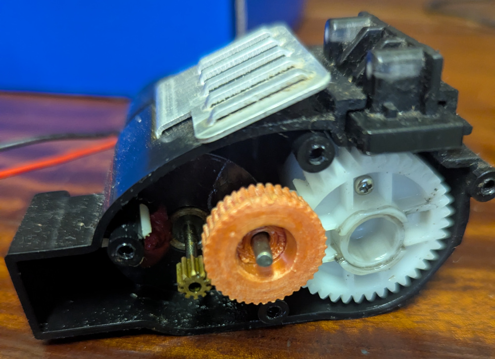
I printed using my XYZPrinting Da Vinci Nano using Elegoo Silk Red Copper PLA filament. While it was clean enough for my purposes so far, I wouldn’t recommend a silk filament for anything finer and I’ve had cleaner prints with some plain black PLA.